
Kitbot Drivetrain
Drivetrain
Section titled “Drivetrain”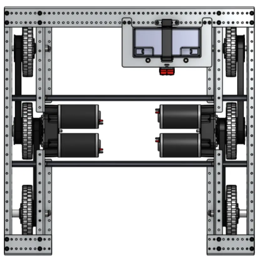
The kitbot uses a four motor tank drive meaning the left and right sides are driven independently by two motors each.
This allows
the robot to move similar to a tank by driving the left and right sides at different speeds.
For this stage, the four drivetrain motors will be referred to as leftLeader, leftFollower, rightLeader, rightFollower.
Motor Controllers
Section titled “Motor Controllers”Motors can not be controlled directly.
Instead, Systemcore talks to a motor controller and the motor controller then drives the motors.
Vendors, such as REV or CTRE, provide classes that can be used to both control and get sensor data, such as position, velocity, and temperature, from their motor controllers.
While each individual type of motor controller has its own class, motor controllers from the same vendor are
mostly interacted with in the same way so this stage will only use the SparkMax for REV code and the TalonFX for CTRE code.
When creating a motor controller object, the physical motor controller’s CAN ID and the CAN Bus ID are given. CAN Bus refers to which of the 5 Systemcore CAN ports, or which CANivore, the device is plugged into. CAN ID is an integer that each CAN device is configured to have. All devices on a given CAN Bus must have a unique ID. Using the combination of CAN Bus and CAN ID SystemCore can give commands to the correct motor controller.
For this exercise the motor controllers will have the IDs:
leftLeader: CAN Bus 0, CAN ID 0leftFollower: CAN Bus 0, CAN ID 1rightLeader: CAN Bus 0, CAN ID 2rightFollower: CAN Bus 0, CAN ID 3
The motor controller objects should be created inside the Robot.java at the top of the class.
This is how the motor controller objects for the left motors will look.
private final int leftLeaderID = 0;public TalonFX leftLeader = new TalonFX(leftLeaderID, CANBus.systemcore(0));private TalonFX leftFollower = new TalonFX(1, CANBus.systemcore(0));For the CTRE code, the CAN ID of the leader motors are stored as a variable since they will be used later on to tell the follower which motor controller to follow. This helps prevent errors from occurring by ensuring that there is a single source of truth for the correct CAN ID. Additionally, CTRE uses a CANBus object to store the CANBus instead of just an integer.
private SparkMax leftLeader = new SparkMax(0, 0, MotorType.kBrushless);private SparkMax leftFollower = new SparkMax(0, 1, MotorType.kBrushless);Since the Spark Max can control both brushed and brushless motors it’s necessary to specify the type as MotorType.kBrushless for motors like a NEO and MotorType.kBrushed for motors like a CIM.
When writing code for a real robot, make sure your motor type is set correctly! Setting a NEO to MotorType.kBrushed will break the NEO.
Now try creating the right motor controllers on your own.
Solution
private final int rightLeaderID = 2;public TalonFX rightLeader = new TalonFX(rightLeaderID, CANBus.systemcore(0));private TalonFX rightFollower = new TalonFX(3, CANBus.systemcore(0));private SparkMax rightLeader = new SparkMax(0, 2, MotorType.kBrushless);private SparkMax rightFollower = new SparkMax(0, 3, MotorType.kBrushless);Motor Controller Configuration
Section titled “Motor Controller Configuration”Motor Controllers have many settings that can be changed such as IDs, motor types, and limits. Vendors provide software, such as REV’s REV Hardware Client 2 and CTRE’s Phoenix Tuner X, to run and configure their devices from a computer. However, it is recommended to configure devices through code to ensure that all motor controllers are properly configured. This is especially useful because it can be easy to forget all of the configurations that need to be added and their proper values.
Motor controllers should usually only configured once and should never be configured periodically during the main robot loop. This is because configuring motor controllers is usually a blocking command meaning the robot code will pause and wait for the motor controller to confirm that it has been properly configured before continuing. This can cause the robot to respond in unexpected and dangerous ways if done while the robot is enabled since motor controllers will not be getting new commands.
For this section only the motor controller’s invert setting will be configured. This setting controls what direction a motor spins when the motor controller is given a command with a positive sign. Since there are two motors on each side of the drivetrain, its important to ensure that the each of the motors on a side move in sync with eachother. This can be accomplished by telling one of the motor controllers to follow the other. This is why one motor is named Leader and the other is Follower. The code tells the Follower to listen to the commands given to the Leader.
The motor controller configuration will be done inside of the constructor for the robot class. Motor Controllers are configured by first creating a motor controller configuration object. This object stores the configuration so it can be changed and shared across different Motor Controllers.
var leftConfig = new TalonFXConfiguration();var leftConfig = new SparkMaxConfig();Next, settings can be changed from their default by calling various functions on the configuration object with their new values.
For the left motors, the invert setting will be true for REV code and Clockwise_Positive for CTRE code.
This will cause the motors to spin in a direction that would drive the robot forward when a positive input is given.
Since the motors on the right side of the drivetrain are facing the opposite direction they would cause the wheels try and drive the robot backwards when given a positive input if they were configured the same way.
Instead they should be configured with an invert setting of false or Counter_Clockwise_Positive so they also drive the robot forward when given a positive input.
leftConfig.MotorOutput.withInverted(InvertedValue.Clockwise_Positive);leftConfig.inverted(true);Finally, the configuration object gets given to the motor controller object. It’s important to remember that settings only get changed when the configuration gets given to the motor controller.
For CTRE Motor Controllers, becoming a follower is a ControlRequest instead of a configuration.
leftLeader.getConfigurator().apply(leftConfig);leftFollower.getConfigurator().apply(leftConfig);
leftFollower.setControl(new Follower(leftLeaderID, MotorAlignmentValue.Aligned));
For REV Motor Controllers, becoming a follower is a configuration so the follower setting gets changed before being applied to the follower motor using the leader motor as the function parameter.
This must happen after the configuration is applied to the Leader so the motor controller doesn’t want to follow itself.
ResetMode.kResetSafeParameters gets to tell the motor controller to reset all unchanged configurations to their default value.
This prevents old configurations from being left on the controller.
PersistMode.kPersistParameters is used so the configuration gets saved on the motor control so it persists even after power is removed.
leftLeader.configure( leftConfig, ResetMode.kResetSafeParameters, PersistMode.kPersistParameters);leftFollower.configure( leftConfig.follow(leftLeader), ResetMode.kResetSafeParameters, PersistMode.kPersistParameters);Now try configuring the right motor controllers on your own. Remember that some of the configurations may be different.
Solution
var rightConfig = new TalonFXConfiguration();rightConfig.MotorOutput.withInverted(InvertedValue.CounterClockwise_Positive);rightLeader.getConfigurator().apply(rightConfig);rightFollower.getConfigurator().apply(rightConfig);
rightFollower.setControl(new Follower(rightLeaderID, MotorAlignmentValue.Aligned));
var rightConfig = new SparkMaxConfig();rightConfig.inverted(false);rightLeader.configure( rightConfig, ResetMode.kResetSafeParameters, PersistMode.kPersistParameters);rightFollower.configure( rightConfig.follow(rightLeader), ResetMode.kResetSafeParameters, PersistMode.kPersistParameters);Arcade Drive
Section titled “Arcade Drive”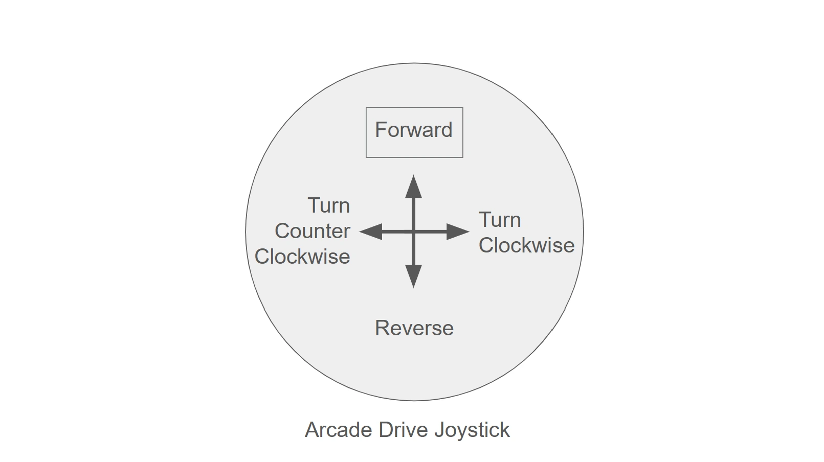
While there are several ways to control a tank drive, this stage will be using arcade drive.
Arcade drive uses the y-axis of a joystick to control how fast the robot drives forward or backward while the x-axis controls how fast the robot rotates clockwise or counter clockwise.
WPIlib provides a class to convert joystick inputs into commands for the motors to follow called DifferentialDrive.
An instance of DifferentialDrive should be created under where the motor controllers were declared.
public final DifferentialDrive drivetrain = new DifferentialDrive(leftLeader::setThrottle, rightLeader::setThrottle);public final DifferentialDrive drivetrain = new DifferentialDrive(leftLeader::setThrottle, rightLeader::setThrottle);Notice how the DifferentialDrive constructor takes the form DifferentialDrive(DoubleConsumer leftMotor, DoubleConsumer rightMotor).
When created the DifferentialDrive is asking for a DoubleConsumer that it can use to drive the left and right motors.
A Consumer is simply a function that takes something as an input so a DoubleConsumer is a function that takes a double as an input when called.
The motorController:setThrottle syntax is used to proved the DifferentialDrive instance with the motor controllers setThrottle() function.
This function commands the motor to run a percentage of their maximum speed, also known as duty cycle, with an input from -1.0 to 1.0.
This allows the DifferentialDrive instance to call the provided motors controller’s setThrottle() functions with the correct duty cycle when provided with input from the joysticks.
The DifferentialDrive instance only needs to be provided with the Lead
motor controller’s setThrottle() functions since the Follower motors will
automatically follow.
An IMU, Inertial Measurement Unit, is a sensor that allows the robot to accurately track its 3d rotation (roll, pitch, and yaw) as it moves around the field.
While there are several vendors that sell very accurate IMUs, this stage will make use of Systemcore’s built in IMU.
An instance of Systemcore’s IMU should be created beneath the differentialDrive.
private OnboardIMU imu = new OnboardIMU(MountOrientation.FLAT);private OnboardIMU imu = new OnboardIMU(MountOrientation.FLAT);While IMUs are accurate they can only measure rotation relative to the initial orientation of the robot when powered on. Therefore, to make full use of an IMU the robot must either start in a known orientation or receive its initial orientation through a vision system.
Check Up
Section titled “Check Up”By now your Robot class in Robot.java should look like this and VS code should not be giving you any errors.
Solution
/** * The methods in this class are called automatically as described in the OpModeRobot documentation. * OpMode classes anywhere in the package (or sub-packages) where this class is located are * automatically registered to display in the Driver Station. If you change the name of this class * or the package after creating this project, you must also update the Main.java file in the * project. */public class Robot extends OpModeRobot {
  private final int leftLeaderID = 0;  public TalonFX leftLeader = new TalonFX(leftLeaderID, CANBus.systemcore(0));  private TalonFX leftFollower = new TalonFX(1, CANBus.systemcore(0));
  private final int rightLeaderID = 2;  public TalonFX rightLeader = new TalonFX(rightLeaderID, CANBus.systemcore(0));  private TalonFX rightFollower = new TalonFX(3, CANBus.systemcore(0));
  public final DifferentialDrive drivetrain =      new DifferentialDrive(leftLeader::setThrottle, rightLeader::setThrottle);
  private OnboardIMU imu = new OnboardIMU(MountOrientation.FLAT);
/** * This function is run when the robot is first started up and should be used for any * initialization code. */public Robot() { var leftConfig = new TalonFXConfiguration(); leftConfig.MotorOutput.withInverted(InvertedValue.Clockwise_Positive); leftLeader.getConfigurator().apply(leftConfig); leftFollower.getConfigurator().apply(leftConfig);
leftFollower.setControl(new Follower(leftLeaderID, MotorAlignmentValue.Aligned));
var rightConfig = new TalonFXConfiguration(); rightConfig.MotorOutput.withInverted(InvertedValue.CounterClockwise_Positive); rightLeader.getConfigurator().apply(rightConfig); rightFollower.getConfigurator().apply(rightConfig);
rightFollower.setControl(new Follower(rightLeaderID, MotorAlignmentValue.Aligned));}/** * The methods in this class are called automatically as described in the OpModeRobot documentation. * OpMode classes anywhere in the package (or sub-packages) where this class is located are * automatically registered to display in the Driver Station. If you change the name of this class * or the package after creating this project, you must also update the Main.java file in the * project. */public class Robot extends OpModeRobot {
private SparkMax leftLeader = new SparkMax(0, 0, MotorType.kBrushless); private SparkMax leftFollower = new SparkMax(0, 1, MotorType.kBrushless); private SparkMax rightLeader = new SparkMax(0, 2, MotorType.kBrushless); private SparkMax rightFollower = new SparkMax(0, 3, MotorType.kBrushless);
public final DifferentialDrive drivetrain = new DifferentialDrive(leftLeader::setThrottle, rightLeader::setThrottle);
private OnboardIMU imu = new OnboardIMU(MountOrientation.FLAT);/** * This function is run when the robot is first started up and should be used for any * initialization code. */public Robot() { var leftConfig = new SparkMaxConfig(); leftConfig.inverted(true); leftLeader.configure( leftConfig, ResetMode.kResetSafeParameters, PersistMode.kPersistParameters); leftFollower.configure( leftConfig.follow(leftLeader), ResetMode.kResetSafeParameters, PersistMode.kPersistParameters);
var rightConfig = new SparkMaxConfig(); rightConfig.inverted(false); rightLeader.configure( rightConfig, ResetMode.kResetSafeParameters, PersistMode.kPersistParameters); rightFollower.configure( rightConfig.follow(rightLeader), ResetMode.kResetSafeParameters, PersistMode.kPersistParameters);}OpModes
Section titled “OpModes”OpModes are a class that registers itself with the driverstation providing a name and robot mode (autonomous, teleop, or utility).
This allows the robot to run different code based on what is selected on the driverstation.
This stage will use classes that extend PeriodicOpMode.
By extending PeriodicOpMode these classes gain a few useful functions that are only called when the OpMode is selected on the driverstation.
start()is called once when the robot transitions from disabled to enabled.periodic()is called repeatedly when the robot is enabled.end()is called once when the robot transitions from enabled to disabled.disabledPeriodic()is called repeatedly when the robot is disabled. Further information about OpModes can be found in this blog post if you would like to learn more.
Two blank PeriodicOpModes, MyTeleop.java and MyAuto.java are provided under the opmode folder.
To control the robot with joysticks a Teleop OpMode needs to be created that periodically gives the DifferentialDrive instance new values from the controller.
First a instance of NiDsXboxController needs to be created.
This class has functions that provide the state of different buttons on the controller.
Multiple controllers can be used at once so the driverstation gives each a slot.
The index provided in the constructor tells the NiDsXboxControllerwhich slot to listen too.
private final NiDsXboxController xboxController = new NiDsXboxController(0);private final NiDsXboxController xboxController = new NiDsXboxController(0);There are different classes for different types of controllers. There is
also a generic Gamepad class that allows you to get button or axis values
by index.
Next, the periodic() method inside of MyTeleop.java' will be used to continually update the DifferentialDriveindex through thearcadeDrivefunction. TheMyTeleopclass has theRobotclass as a parameter in its constructor. This allows the Opmode to access the methods and fields of theRobot` class.
@Overridepublic void periodic() { /* Called periodically (set time interval) while the robot is enabled. */ robot.drivetrain.arcadeDrive(-xboxController.getLeftY(), xboxController.getRightX());/* Called periodically (set time interval) while the robot is enabled. */@Overridepublic void periodic() { robot.drivetrain.arcadeDrive(-xboxController.getLeftY(), xboxController.getRightX());At this point MyTeleop.java should look like this
Solution
@Teleoppublic class MyTeleop extends PeriodicOpMode {  private final Robot robot;  private final NiDsXboxController xboxController = new NiDsXboxController(0);

  /** The Robot instance is passed into the opmode via the constructor. */  public MyTeleop(Robot robot) {    this.robot = robot;  }
@Override public void periodic() { /* Called periodically (set time interval) while the robot is enabled. */ robot.drivetrain.arcadeDrive(-xboxController.getLeftY(), xboxController.getRightX());@Teleoppublic class MyTeleop extends PeriodicOpMode { private final Robot robot; private final NiDsXboxController xboxController = new NiDsXboxController(0);
/** The Robot instance is passed into the opmode via the constructor. */ public MyTeleop(Robot robot) { this.robot = robot; }
/* Called periodically (set time interval) while the robot is enabled. */ @Override public void periodic() { robot.drivetrain.arcadeDrive(-xboxController.getLeftY(), xboxController.getRightX());